Skip to content

Building the Fleet: From Hull and Aircraft to a Working Anchor

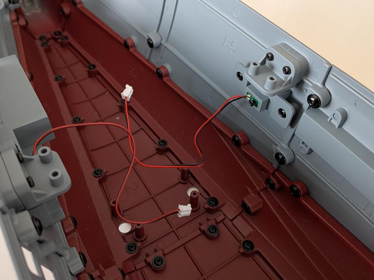
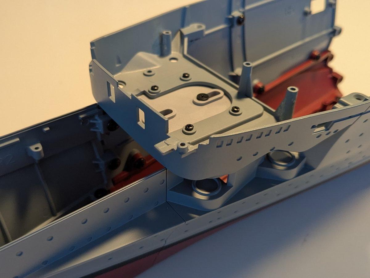
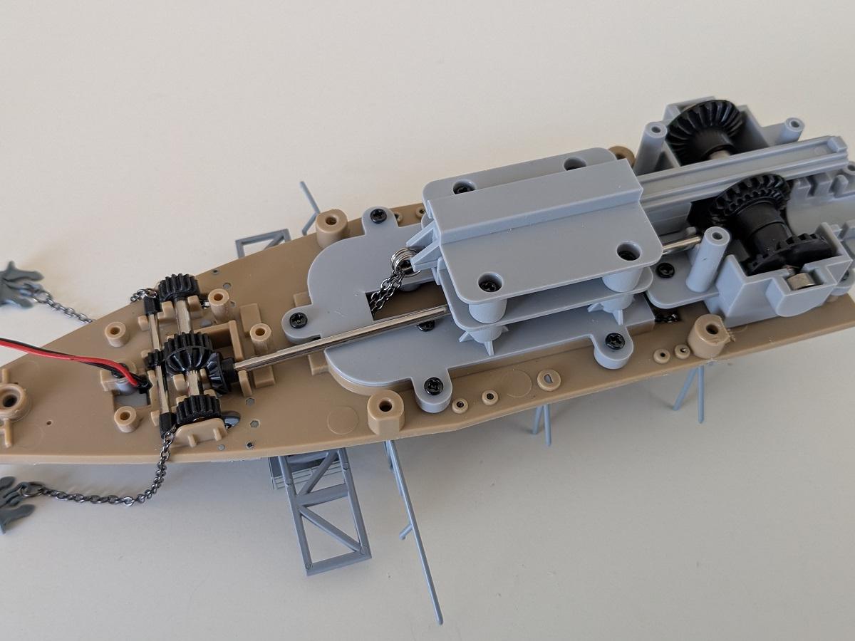
Construction begins with the initial assembly of the bow and a Ju 87 dive bomber, including electrical testing of the aircraft's propeller. The model's foremost deck is then built, featuring a 3.7 cm anti-aircraft gun with a blinking LED for simulated firing. Hull construction commences with the addition of keel and hull sections. As the build progresses, a second Ju 87 is added, and photo-etched parts are used for railings and platforms. The final steps focus on the moving anchor mechanism, with the installation of both anchors, their chains, and a complex system of cogwheels and spools below the deck.

Step 1/140: Initial Assembly and Electrical Testing

2 Images

The initial stage of construction involves several key components: the two foremost bow parts, a Ju 87 dive bomber, and a test board designed to verify the model's electrical functions.

The bow parts are screwed together, forming the initial section of the model's structure. Following this, the Ju 87 is equipped with its propeller. The dive bomber is then placed on the test board to immediately verify the proper function of its engine, ensuring everything is operational from the outset.

Step 2/140: Foremost Deck Assembly and Weaponry

2 Images

This step involves assembling the foremost deck section and integrating its key features. The deck parts are carefully put together, and its wooden cover is affixed, providing a realistic finish. Various details are attached to this deck covering, enhancing its authenticity.

A pivotal addition in this phase is the 3.7 cm AA gun. This gun isn't just a static model; it simulates firing with a blinking LED to represent muzzle flash. The gun is mounted on its platform and fitted with this pre-tested LED. Just like in the previous step, the gun's LED function is tested with the test board from Step 1, ensuring its operational readiness.

Step 3/140: Catapult Assembly and Ju 87 Preparation

4 Images

This step focuses on preparing the model's first catapult and readying the previously assembled Ju 87 dive bomber for launch.

The first catapult is assembled and then checked for free movement, ensuring it operates smoothly. While an electrical motor will position it later, this initial check confirms its mechanical readiness.

The Ju 87 from Step 1 receives its landing gear legs and is armed with four bombs. Finally, the completed Ju 87 is mounted onto its launch rack on the catapult. A propeller function test is then performed while the Ju 87 is on the catapult, verifying its operational status just before potential deployment.

Step 4/140: Hull Construction

3 Images

This segment, involves adding a keel section and the initial upper starboard hull section to the model's structure. This process contributes to the overall growth of the hull.

The installation of three support strut parts on the lower deck is also part of this step, these components are intended to support the upcoming flight deck. It was observed that the largest of these struts presents a challenge in fitting precisely into its designated holes on the flight deck.

Future steps will require the use of screws to secure hull sections. It is anticipated that appropriate tools will be beneficial, particularly when attaching the opposing hull section.

Step 5/140: A left hull section

4 Images

Another hull section is mounted on the left side of the main structure. Fastening the upper screw can be a bit challenging due to the limited working space.

On the lower deck, three more support struts and the right inclined elevator (used for the catapult trolleys) are installed. As with the previous step, some of the struts don't fit perfectly, so care must be taken to avoid damaging them.

Step 6/140: The next hull section

3 Images

This was a quick build. Another hull section is fastened to the left side of the fuselage structure. On the lower deck, the left inclined lift for the cataplut carts is attached. Unfourtunally one of the previous added struts broke, will glue this later to prevent this breaking again.

Step 7/140: Next hull part and port-side anchor windlass

3 Images

Another section of the hull is added, but fastening the screws along its side is quite tricky due to the limited working space.

The other component is the port-side anchor windlass, assembled from four parts. In later steps, it will become part of the mechanism that moves the anchor chains.

Step 8/140: Starboard anchor windless and another hull segment

3 Images

A longer underwater hull section is fitted to the port side of the structure, doubeling the length of the hull. The starboard anchor windlass is then assembled.

Both anchor windlass are now buid and provisionally added to the deck.

Step 9/140: Photo etched details

3 Images
Photo-etched parts are often quite fragile, and it's surprising to see them included in a model like this. They are used to create realistic railings and the catapult trolley lift platforms.

Because the material is a bit thicker than what's typically used for 1/350 or 1/700 scale kits, it was tricky to remove the parts from the frame without damaging them. A bit of super glue was necessary to attach them to the deck in their proper positions.


Step 10/140: The second aircraft and gearbox

4 Images

A second Ju 87 is included at this stage, this time built without an electric motor. 

An engine and gearbox housing is installed on the underside of the lower deck, which will later form part of the mechanism used to operate the ship’s anchor chains.


Step 11/140: Another hull part and first anchor

3 Images
This is the starting point for the moving anchor construction.
In addition to adding another hull part, the main focus here is to begin building the anchor mechanism by positioning the port anchor and its chain, as well as adding smaller details to the lower deck.

Step 12/140: A new hull part

3 Images

The construction of the hull's port side continues with the addition of a new part, a key section that will eventually house the forward 15 cm guns. Additionally, some smaller details are being added to the lower deck.

Step 13/140: Continue with the anchor mechanism

2 Images

The starboard anchor is now added, and more mechanical components are put in place for the anchor mechanism below the lower deck. This includes separate cogwheels at the front and back. The front wheels will later be responsible for moving the chains, while the rear wheels will simultaneously turn the anchor spools.

Step 14/140: Mechanical work for the anchor mechanism

Work on the mechanism for the movable anchors continues in this step.

At the rear of the deck, the anchor spill is connected to the anchor transport rollers at the front by a shaft with bevel gears. The anchor chains are fastened to a toothed rack, and by shifting this rack back and forth, the anchors can be lowered or raised.