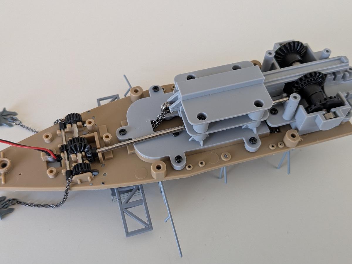
Skip to content

Hull and Flight Deck Assembly

In this phase of the Graf Zeppelin build, work transitions from the internal mechanical systems to the ship’s external structure. The anchor mechanism is completed and tested, marking the end of the early internal assembly stages. Construction then focuses on the hull, where multiple sections are fitted to form the bow, followed by the installation of a large keel piece that adds significant rigidity to the forward structure.

Once the hull is stabilized, assembly of the flight deck begins. The deck features a combination of plastic and wooden elements, reinforced with adhesive for durability, and includes numerous small details and photo-etched components. Lighting is introduced for the first time, with LEDs installed for both internal illumination and future signal lighting on the deck.

These steps collectively mark the transition from the foundational framework to the visible superstructure of the carrier.

Step 15/140: Anchor mechanism gearbox

This step completes the anchor mechanism gearbox.

It begins by closing the gearbox housing, followed by the installation of the electric motor which drives the mechanism. Once the gearbox was lubricated and installed, a successful test with the test board was conducted to confirm proper function.

Step 16/140: Anchor end switch and another Ju 87

The anchor mechanism is finalized by installing the end switch for the moving mechanism.

Additionally, another Ju 87 is "build" by adding the landing gear and bombs. Surprisingly - and I do not know why, the propellor of the Ju 87 from step 10 has to be replaced by a different one. I cannot see any difference, so I have no idea why this replacement is required.

Step 17/140: Hull parts

Beginning with this stage, several hull sections will be attached to the bow of the Graf Zeppelin. Compared to the earlier construction steps, the upcoming ones may feel a bit more routine and less eventful.

Step 18/140: Next hull parts

Although attaching the new hull sections to the main structure may seem straightforward, there’s one challenge: the limited working space makes it difficult to tighten the screws using the provided tools. As a result, installing each new hull segment can take longer than expected.

Step 19/140: Continuing on the starbord hull

The next starboard hull segment is installed, completing the assembly of the forward hull section.

Step 20/140: Keel part to complete the forward hull section

A large keel section is installed, completing the forward hull assembly. While the hull had been somewhat unstable up to this point, the keel adds significant rigidity to the bow area.

The two openings in the keel will later accommodate the model’s display stand.

The hull now weighs approximately 1.5 kg.

Step 21/140: Start with flight deck assembly

This stage begins with the assembly of the flight deck. It includes the plastic flight deck base, a wooden deck covering, several small detail parts, and photo-etched components.

Although the wooden deck covering features a self-adhesive backing, it is advisable to reinforce it with additional adhesive, such as superglue or wood glue, to ensure a secure fit.

Additional small parts are attached to both the upper and lower surfaces of the flight deck, and the movable catapult constructed in Step 3 is integrated into the deck structure at this stage.

Step 22/140: Detailing the flight deck

Several small details are fitted to both the top and underside of the flight deck, with particular attention paid to the air-pressure containers mounted beneath the deck.

A first LED is also installed at this stage; it will later illuminate the lower deck.

Step 23/140: Continue detailing the flight deck

Additional details are added to both the upper and lower surfaces of the flight deck.

A second LED is installed at this stage, intended to serve as signal lighting on the flight deck in the later assembly.

Step 24/140: Catapult Mechanics

In this stage, work continues on the catapult mechanism.


The electric motor for the extendable catapult is installed and tested for proper operation. Additional components for the system will be assembled in the following steps.