Skip to content

Build Progress – Guns Online and the Hull Takes Shape

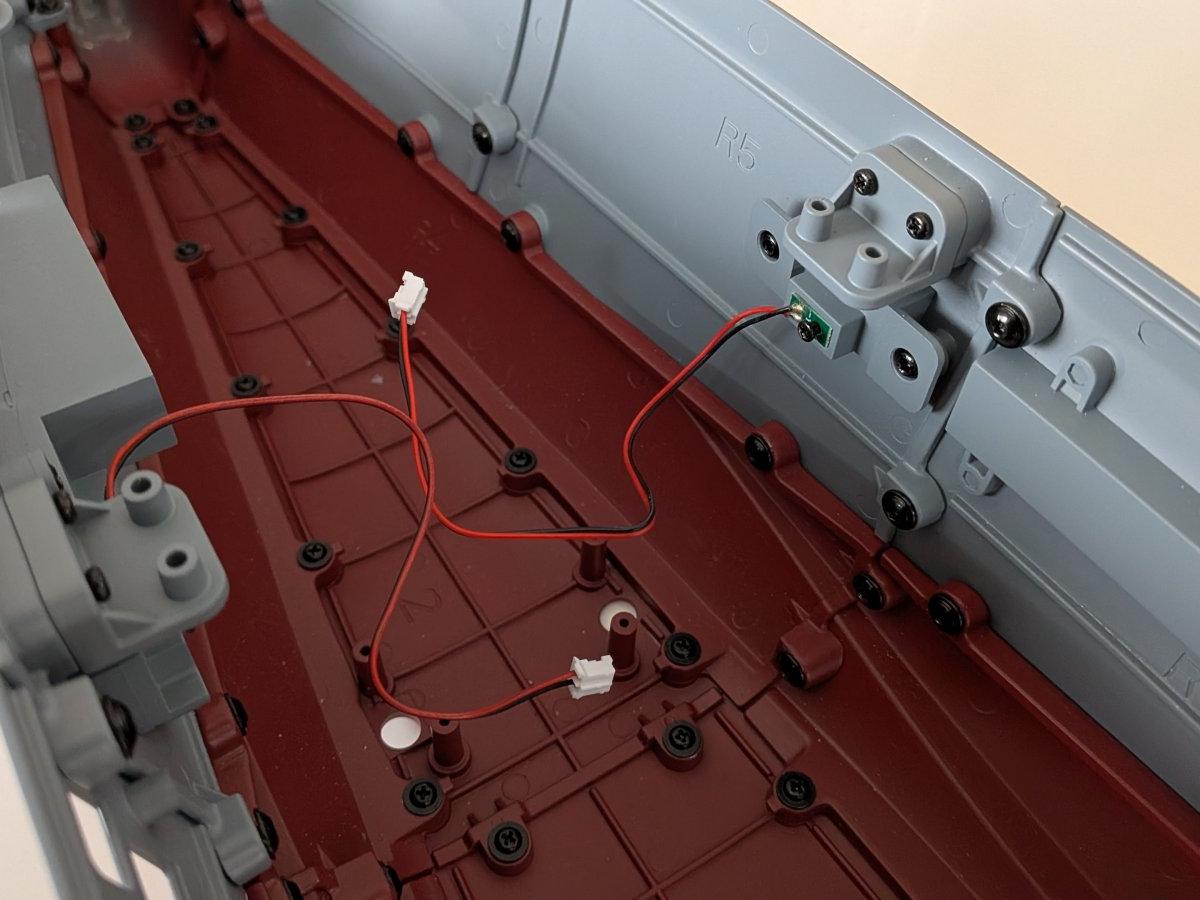
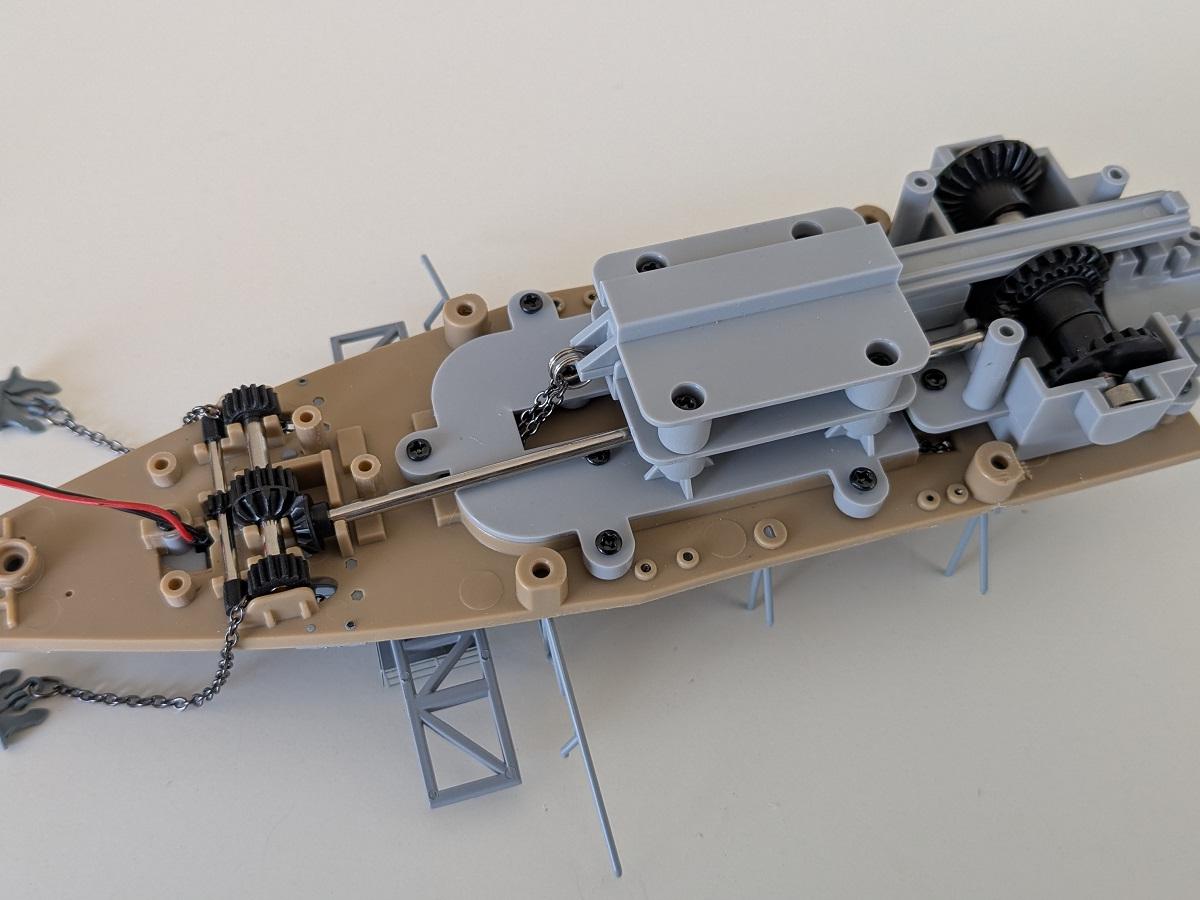
With these stages, the model makes a decisive leap forward in both presence and functionality. The forward 15 cm gun battery comes to life, adding mechanical movement and illuminated firing effects that give the bow a striking, almost cinematic character. The integration of motors, wiring, and control components marks a clear transition from static construction to an increasingly dynamic display piece.

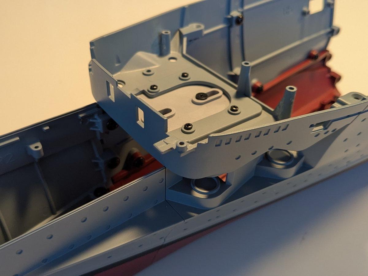
At the same time, the hull undergoes a dramatic transformation. Section by section, the carrier grows in length and mass, pushing past the halfway mark and beginning to convey the true scale of the Graf Zeppelin. Structural extensions below and above the waterline, detailed railings, navigation lights, and keel elements steadily turn the framework into a formidable warship silhouette.

By the end of this phase, the ship not only feels larger and heavier, it feels operational. And with aircraft assembly continuing in parallel, the groundwork for the future flight deck is clearly beginning to emerge.

Step 29/140: First 15 cm guns

In this step, the first of the forward 15 cm gun mounts are installed.

The guns, which are equipped with LEDs to simulate muzzle fire, are fitted into the casemattes and then connected to the traverse mechanism. Care must be taken not to tighten the screws too much, as this would prevent the moving mechanism from operating correctly.

Step 30/140: Continue with forward 15 guns.

An additional 15 cm gun is installed and connected to the traverse mechanism.

In preparation for the next construction steps, a small switchboard is added. This unit will later serve as the central junction, combining all electrical wiring required for gun movement and firing.

Step 31/140: Completing the forward 15 cm guns

This step completes the installation of the forward 15 cm gun turrets.

The final gun is fitted, the drive motor for the movement mechanism is installed, and all cables are connected to the switchboard. A functional test is then carried out, confirming both the simulated firing effect—represented by LEDs in the gun barrels—and the elevation movement of the guns.

While the guns do not move independently and instead operate together, which slightly reduces realism, the mechanism works reliably and adds a noticeable dynamic feature to the model.

Step 32/140: Extending the hull

After completing the mechanical installation for the forward guns, this step—and the following ones—focuses on extending the hull. Beginning with the addition of a new underwater section on the port side, the hull length is now almost doubled.

Step 33/140: Building the Hull – Reaching the Halfway Mark

In this step, another section of the port-side hull is installed.

With this addition, the hull has now reached a length of approximately 70 cm, which is about half of the model’s final size. Since the corresponding starboard hull sections have not yet been fitted, there was ample working space, making the installation straightforward and allowing the screws to be tightened easily.

Step 34/140: Hull Detailing Step: PE Railing and Port Light Installation

This time, a photo-etched railing and an internal cover for several hull openings are added. A LED is also installed, which will serve as the port-side navigation light.

Step 35/140: Continue with hull starboard side

With this step, construction of the starboard side of the hull continues. Although only two screws are required, the confined space inside the hull makes tightening them somewhat tricky.

At this stage, the ship’s weight has now exceeded 2 kg.

Step 36/140: Starboard Hull

Work on the hull continues in this step.

An upper hull segment is added to the ship. Since construction has now reached the widest part of the hull, fastening the screws is much easier compared to the cramped and narrow space in the bow section.

Step 37/140: Navigation lights

The starboard hull segment from the previous step was updated with an internal cover to close the hull openings. Unusually, this part is not screwed in place; instead, it is glued for this installation.

The green starboard navigation light was then installed and successfully tested.

Step 38/140: A keel section

Not much work was required in this step — a keel section was added to the hull structure.

This improves the overall stability of the hull. The port and starboard sides are built asymmetrically due to the openings in the upper hull structure, which differ on each side.

Step 39/140: Another Ju 87 dive bomber

This step includes the assembly of a fifth Ju 87 dive bomber. The propeller, landing gear, and four bombs must be attached and securely glued in place.

In addition, two mounting brackets are fitted to the hull. These will most likely serve as the structural supports for the future flight deck.